Site Sponsors & Vendors
Page 2 of 3 FirstFirst 123 LastLast
Results 11 to 20 of 29

Thread: Looking for opinions

  1. #11
    Senior Member
    Join Date
    Jul 2011
    Posts
    105
    Post Thanks / Like

    Default

    Quote Originally Posted by STL_G8GT View Post
    Im glad you found this, but I hate reading things like this... makes me rethink my cam swap, and if I paid enough attention when this reconnected!
    When my o-ring was pinched (and you can see how bad it was pinched!), I had the following:

    Coasting = 3BAR (~43.5PSI)
    Revving = 3BAR (~43.5PSI) It would never go above 3BAR, ever.
    Idle = 0 - 2.5BAR (~0 - 35PSI)

    Now that the o-ring is sitting properly I had this:

    Coasting = 3BAR (~43.5PSI)
    2000+RPM = 3 - 4.5BAR (43.5 - 55PSI (capped with the relief valve in oil pan)
    Idle = 3BAR (~43.5PSI) It never drops lower than this now.

    Overall, with the pinched ring, there was adequate oil pressure during coasting but the oil was getting frothy and aerated from the pump sucking in just as much air as oil. Because of that air being sucked in, the pressure couldn't build appropriately to rise with higher RPM. When I was idling, it was just not pretty. My point here is that it's so dangerous because the car worked just enough to operate but there was clearly something wrong. Luckily we identified it early and I only put a couple hundred miles on the car like that of EASY driving. I'm confident something would give with prolonged, regular use.

    Hopefully our learning (and some misery) will help someone else not have to go through it. A piece of rubber shouldn't be so pivotal in an engine, but it is. Learning definitely occurred these last few weeks. If I never have to drop that oil pan again, I will not complain.
    Last edited by BloKKem; 01-16-2012 at 07:36 PM.
    2008 GT - 97000 miles and counting
    VMS 1.5 cam / CNC ported LS3 heads / LS7 lifters / Rotofab CF CAI / SLP LT Headers / Corsa / VMS Tune
    Maverick Man CF hood / 20" Breyton GTS

  2. #12
    Senior Member
    Join Date
    Jul 2011
    Posts
    105
    Post Thanks / Like

    Default

    The conversations on the different forums are taking different directions but the information I want to provide is good for everyone so if these seem out of order, so be it. The information is what's relevant :P

    To remove the oil pan....

    Here is what we did: Obvious up front: Disconnect the battery and drain the oil, lol

    1. Remove the plastic front undercarriage. There are 4x 6 or 7mm bolts and a ton of plastic push clips. Finesse it out, it just takes a little love and some patience to get the inside plastic lip to slide out. It will crack your bumper if you force it out!

    2. Remove the 13mm (I think) bolt from the steering column clasp. (You will need to put your key in to unlock your steering wheel to get this to line up and put back on, most likely.)

    3. the 2 15mm rack & pinion bolts on each side come out (total of 4). There is a 15mm black nut welded to the frame of the car on the bottom side. The 15mm bolt that you want to take out is on the top of the frame. (A tip here, spray some WD-40 on the bottom end of this bolt that sticks out the bottom of the black nut, if you don't, you will wish you did after trying to crank all 4 of these out!)

    4. Remove the 18mm (I think) nut from the tie rods on each hub and knock that bolt out with a hammer. There are a couple "wire management" type bolts near the front of the oil pan and rack & pinion that have to come out too, I think they are like 8 or 10mm. After doing 1, 2, & 3, the rack and pinion can slide nicely forward. (being able to slide this rack & pinion and wiring trays out of the way makes it incredibly easy to get those 4 front bolts on the oil pan out from the bottom.)

    5. Remove the two front motor mount bolts from the bottom of the car.

    6. Obviously all the oil pan bolts come out, don't forget the 2 long 10mm bolts at the bottom rear, near the filter OR the 2 13mm or 15mm (can't remember) that bolt through the bell housing in the oil pan horizontally.

    7. Jack the engine up, we used a solid spot on the transmission and an 8 x 6 piece of wood to raise it. I think we raised about a couple inches.

    8. Oil pan slides right out but be cautious of the oil pick up tube since this is attached to the windage tray and oil pump. The pan will slide right out but the front lip needs to come down enough to slide under and past the oil pickup tube. This is why moving the rack & pinion makes doing that so easy. With it in the way and the engine not lifted, there is no conceivable way, that we saw, to slide that pan past. I'm confident in saying that it's impossible. Also, don't forget to remove the wiring harness from the passengers side of the pan before sliding it out.
    2008 GT - 97000 miles and counting
    VMS 1.5 cam / CNC ported LS3 heads / LS7 lifters / Rotofab CF CAI / SLP LT Headers / Corsa / VMS Tune
    Maverick Man CF hood / 20" Breyton GTS

  3. #13
    Addicted Member mooredata's Avatar
    Join Date
    Oct 2009
    Location
    Illinois
    Posts
    540
    Post Thanks / Like

    Default

    Man I was thinking of doing a VMS Head\CAM setup. Is this something they should do with a DOD system? i'VE read some where that the stock oil pump uses more pressure with a AFM system then with a non-DOD CAM installed, the extra pressure is not needed. Also, why # 6 before your Head \ Cam install still trying to sort this all out. thanks for the post.

  4. #14
    VIP Member UGotSmkd's Avatar
    Join Date
    Dec 2008
    Location
    Houston, TX
    Posts
    1,246
    Post Thanks / Like

    Default

    Quote Originally Posted by BloKKem View Post
    (edit, had cylinder number mislabeled.)

    I have always had what I would consider a repetitive ticking sound in my G8. It's never been anything like lifter tick from what I hear in the youtube videos but I have a sound nonetheless.

    We recently did the VMS head and cam swap and noticed the #5 cylinder was black BLACK compared to all the rest. When I was stock, this was always the vicinity of where the sound appeared to be coming from when standing in front of the engine. I always thought it could be the fuel injector making the sound and considered the possibility of it being DOD lifter tick but I was never sure.

    Post-head/cam install, the sound is back. That pretty much cancels out lifter noise since all new lifters have been installed but the sound is definitely coming from the same area. I'll try to explain when the sound is most prevalent: When I first start the car, everything sounds fine. There is typical valvetrain noise but it sounds good and healthy. Once I let the car warm up and start stepping on it 3-5k RPM, the ticking starts and it is very loud in the cabin of the car and underneath if I drop down and listen. It can be heard standing over the engine bay but a combination of all the other engine noises makes it a pain to focus on it.

    Here is where it gets very difficult though, if I put it in PARK and step out with my stethoscope, I can't find where the sound is coming from. AND, if I take too long, it fades as the car idles. From my understanding, if it were lifter tick, it would be present at idle and be easily identifiable. So, I started thinking that maybe it was exhaust leak from the header. A trip to Jiffy Lube to get fuel injectors cleaned pretty much negated that theory since the smoke created from the process would have appeared in any leaks, and it did not come out anywhere other than my exhaust tips.

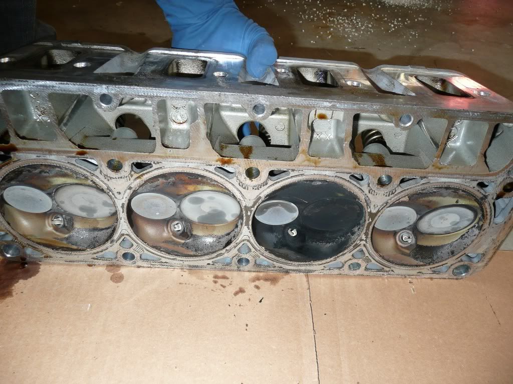
    So now, I am out of ideas. I keep going back to that black #6 cylinder and trying to figure out why it was like that. New lifters, cam, pushrods, rocker arm trunnions, and spark plugs have been installed as of a few days ago so it has to be something that is still present in the system that was there before my recent install.

    Looking for ANY help or ideas, I'm out there all evening with the car running, trying to figure it out. Perhaps this picture will help show that when I say black #6, I mean BLACK.


    VIDEOS added:

    Car warming up, sound is what is to be expected with the valvetrain. The tick is barely audible in this clip, as it always is, but it is not prevalent yet since I haven't revved the engine yet.


    This is a 5 minute video but if you have the time, list to it to hear the transition of when the tick occurs from the beginning when I am simply revving the engine to when it begins afterwards:


    This is the cammed exhaust note. It's sexy, but you can still hear that tick coming from the engine bay even from behind the car. This ticking sound is one of those sounds that almost appears to get louder the further you are away from it.
    Looks like that one cylinder has a layer of carbon buildup.
    2008 White Hot G8 GT - SOLD
    Power: 430 LS3, Vararam, ARH 1 7/8 LTs w/ Magnaflow Axleback, Patrick G. Tune
    Looks: 6000k HIDs, 19" Sport wheels
    Suspension: BMR Rear Trailing Arms, Subframe Bushings, and Toe Rods, Koni Sport Shocks/Struts, H&R Sport Springs
    423/406


    Current - BMW 2007 335i


  5. #15
    Senior Member
    Join Date
    Jul 2011
    Posts
    105
    Post Thanks / Like

    Default

    Quote Originally Posted by mooredata View Post
    Man I was thinking of doing a VMS Head\CAM setup. Is this something they should do with a DOD system? i'VE read some where that the stock oil pump uses more pressure with a AFM system then with a non-DOD CAM installed, the extra pressure is not needed. Also, why # 6 before your Head \ Cam install still trying to sort this all out. thanks for the post.
    When you do a typical cam set up, you are deleting the DOD system from your car. After my install, there is no more DOD hardware in my G8. There are some guys in the forum that have inquired about putting an aftermarket cam in and retaining the DOD functionality but I wouldn't be able to speak to that since that is the complete opposite of what I did. The picture of that #5 cylinder head in my original post is something that we removed. Now, granted, the heads aren't considered DOD hardware but I upgraded them during my DOD-delete. My ticking problem that the videos demonstrate is not related to that #5 cylinder at all. In the beginning of our troubleshooting, I was unsure of what could have been related so I looked at everything abnormal at once.

    I'm not sure on that #5 cylinder and why there was so much carbon build up. I have been dealing with troubleshooting the new hardware I put in over the last few weeks so I haven't had time to really get in the weeds with the stock stuff we took out. I'll be looking into it when I clean the stock heads we removed. Right now I'm assuming there was a problem with the valve on that #5 cylinder or something funky going on with the lifter that was serving #5. I'll definitely post back if something definitive or suggestive develops.

    As far as the oil pump is concerned in response to what you wrote, I think what you're referring to is the stock pump on the G8 being suited for DOD and being an extremely high flow pump. Where you run into problems is guys that use this pump on different capacity oil pans and you run the risk of draining the pan because there is simply not enough oil. Having a 8.8 quart wet sump pretty much alleviates that from being a problem in our cars. Deleting DOD from your G8 and having a high flow oil pump left from the stock setup is ideal in my opinion. The catch is that there is that 55PSI pressure relief valve in the oil pan left over that was necessary for the DOD hardware thresholds. Some guys with DOD-delete installs removed that pressure relief valve, some did not. I left mine in there.
    Last edited by BloKKem; 01-16-2012 at 09:59 PM.
    2008 GT - 97000 miles and counting
    VMS 1.5 cam / CNC ported LS3 heads / LS7 lifters / Rotofab CF CAI / SLP LT Headers / Corsa / VMS Tune
    Maverick Man CF hood / 20" Breyton GTS

  6. #16
    Lucky SOB G8GT721's Avatar
    Join Date
    Dec 2008
    Location
    MA
    Posts
    4,246
    Post Thanks / Like

    Default

    In for later use


    Sent from my iPhone using Tapatalk

    2008 White Hot G8 GT

    (new)499RWHP/474RWTQ Mustang Dyno
    (old)451RWHP / 498RWTQ Mustang Dyno
    1/4=11.400@118.7 17" Drag Radials, stall, cam 1.77 60'
    1/4=12.004@120.6 17" Drag Radials 2.03 60'
    1/4=12.270 @118.3 on 18" All Seasons 2.08 60'
    SLOWHAWK Tuned

    If you can't say anything intelligent, say something loud and stupid
    My Garage

  7. #17
    VIP Member STL_G8GT's Avatar
    Join Date
    Jul 2009
    Location
    Estes Park, CO
    Posts
    5,001
    Post Thanks / Like

    Default

    Do you know the torque values of all bolts removed? Also, did you dab rtv at the junction of front and rear cover when reinstalling the pan? I have a slight seep and want to address it before I add boost to the system. Any pics? Not really familiar with suspension components. Will this impact the alignment?

    Quote Originally Posted by BloKKem View Post
    The conversations on the different forums are taking different directions but the information I want to provide is good for everyone so if these seem out of order, so be it. The information is what's relevant :P

    To remove the oil pan....

    Here is what we did: Obvious up front: Disconnect the battery and drain the oil, lol

    1. Remove the plastic front undercarriage. There are 4x 6 or 7mm bolts and a ton of plastic push clips. Finesse it out, it just takes a little love and some patience to get the inside plastic lip to slide out. It will crack your bumper if you force it out!

    2. Remove the 13mm (I think) bolt from the steering column clasp. (You will need to put your key in to unlock your steering wheel to get this to line up and put back on, most likely.)

    3. the 2 15mm rack & pinion bolts on each side come out (total of 4). There is a 15mm black nut welded to the frame of the car on the bottom side. The 15mm bolt that you want to take out is on the top of the frame. (A tip here, spray some WD-40 on the bottom end of this bolt that sticks out the bottom of the black nut, if you don't, you will wish you did after trying to crank all 4 of these out!)

    4. Remove the 18mm (I think) nut from the tie rods on each hub and knock that bolt out with a hammer. There are a couple "wire management" type bolts near the front of the oil pan and rack & pinion that have to come out too, I think they are like 8 or 10mm. After doing 1, 2, & 3, the rack and pinion can slide nicely forward. (being able to slide this rack & pinion and wiring trays out of the way makes it incredibly easy to get those 4 front bolts on the oil pan out from the bottom.)

    5. Remove the two front motor mount bolts from the bottom of the car.

    6. Obviously all the oil pan bolts come out, don't forget the 2 long 10mm bolts at the bottom rear, near the filter OR the 2 13mm or 15mm (can't remember) that bolt through the bell housing in the oil pan horizontally.

    7. Jack the engine up, we used a solid spot on the transmission and an 8 x 6 piece of wood to raise it. I think we raised about a couple inches.

    8. Oil pan slides right out but be cautious of the oil pick up tube since this is attached to the windage tray and oil pump. The pan will slide right out but the front lip needs to come down enough to slide under and past the oil pickup tube. This is why moving the rack & pinion makes doing that so easy. With it in the way and the engine not lifted, there is no conceivable way, that we saw, to slide that pan past. I'm confident in saying that it's impossible. Also, don't forget to remove the wiring harness from the passengers side of the pan before sliding it out.
    2009 PBM G8 GT
    Pat G 218/226 & TSP Dual 660s, ARP Bits, DSteck Tuned, Magnacharger Chrome 2300 1:1, RCR Ported/Polished TB, Blower, & L92 Heads w/ LS3 intake valves, Smith Brothers Trunion Bushing Kit, ARH 1 7/8 Magnaflow MidMuff/Solo Axlebacks, RotoFab, VaporWorx PWM 1:1 fuel system, ID1050x injectors
    Mike Norris Motorsports Catchcan, AEM 30-4100, JHP Boost/Fuel Gauge Pod
    TSW Nurburgring Matte Gray 18" w/Nitto 555 & 555R, Satin Black SS Brembo Fronts, BMR Trailing Arms, Pedders Sway Bars, Whiteline Bushings
    Gloss Black Valve Covers, 6k HID, V6 Handles, Interior/License Plate LEDs, Debadged, Holden Black Trim, Polk Dxi, GXP diffusor, a few bits from Crazy Paul

    Originally Posted by TonyKarter
    Anyone who has ever worked on a car has been in your position, and sitting cross-legged on a concrete floor with a dim shop light is its own kind of hell... Chalk it up as one of the rites of passage.
    RIP Charlie - GRRRR8
    RIP Chris Wells - Panzer Leader

  8. #18
    Senior Member
    Join Date
    Jul 2011
    Posts
    105
    Post Thanks / Like

    Default

    Quote Originally Posted by STL_G8GT View Post
    Do you know the torque values of all bolts removed? Also, did you dab rtv at the junction of front and rear cover when reinstalling the pan? I have a slight seep and want to address it before I add boost to the system. Any pics? Not really familiar with suspension components. Will this impact the alignment?
    Yes, we did dab some RTV on the front corners of the oil pan where it comes in contact with the front cover.

    As far as the unbolting of the rack & pinion and the tie rods, it does not affect the alignment. I'll get some pictures up tomorrow to show exactly what bolts it is that I am referring to that we worked with to get everything loose.
    2008 GT - 97000 miles and counting
    VMS 1.5 cam / CNC ported LS3 heads / LS7 lifters / Rotofab CF CAI / SLP LT Headers / Corsa / VMS Tune
    Maverick Man CF hood / 20" Breyton GTS

  9. #19
    VIP Member STL_G8GT's Avatar
    Join Date
    Jul 2009
    Location
    Estes Park, CO
    Posts
    5,001
    Post Thanks / Like

    Default

    Quote Originally Posted by BloKKem View Post
    Yes, we did dab some RTV on the front corners of the oil pan where it comes in contact with the front cover.

    As far as the unbolting of the rack & pinion and the tie rods, it does not affect the alignment. I'll get some pictures up tomorrow to show exactly what bolts it is that I am referring to that we worked with to get everything loose.
    Thanks. Torque values would be extra win!!!!
    2009 PBM G8 GT
    Pat G 218/226 & TSP Dual 660s, ARP Bits, DSteck Tuned, Magnacharger Chrome 2300 1:1, RCR Ported/Polished TB, Blower, & L92 Heads w/ LS3 intake valves, Smith Brothers Trunion Bushing Kit, ARH 1 7/8 Magnaflow MidMuff/Solo Axlebacks, RotoFab, VaporWorx PWM 1:1 fuel system, ID1050x injectors
    Mike Norris Motorsports Catchcan, AEM 30-4100, JHP Boost/Fuel Gauge Pod
    TSW Nurburgring Matte Gray 18" w/Nitto 555 & 555R, Satin Black SS Brembo Fronts, BMR Trailing Arms, Pedders Sway Bars, Whiteline Bushings
    Gloss Black Valve Covers, 6k HID, V6 Handles, Interior/License Plate LEDs, Debadged, Holden Black Trim, Polk Dxi, GXP diffusor, a few bits from Crazy Paul

    Originally Posted by TonyKarter
    Anyone who has ever worked on a car has been in your position, and sitting cross-legged on a concrete floor with a dim shop light is its own kind of hell... Chalk it up as one of the rites of passage.
    RIP Charlie - GRRRR8
    RIP Chris Wells - Panzer Leader

  10. #20
    Senior Member
    Join Date
    Jul 2011
    Posts
    105
    Post Thanks / Like

    Default

    Quote Originally Posted by STL_G8GT View Post
    Thanks. Torque values would be extra win!!!!
    I'll be honest with you, when it came to the rack & pinion and tie rod bolts, we just bolt them down nice and tight. There was no way to get a torque wrench up there on those rack & pinion bolts from the angle we were working.

    On to some pics:

    Here is the tie rod bolts (just a picture of the passengers side). Unbolt that nut on the top and take a nice mallet/hammer and hit that bolt down. Use some force because it's in there good.


    The rack & pinion has a total of 4 bolts. This picture shows the two on the drivers side. These bolts are what needs to be unbolted to loosen the rack & pinion. (In the picture following this one, read where I messed up, and where maybe you can learn from my mistake and do it the right way.)


    The rack & pinion also has a total of 4 black nuts that can be accessed from underneath the car. DO NOT do what I did and attempt to take the nut off of the underside of the bolt. These nuts are welded onto the frame of the car and are meant to have the bolt in the previous picture removed from them, NOT the other way around. (pictures for reference on what NOT to put a socket on.)


    At some point, just removed this bolt from the steering column so that you can freely turn the wheels to move that rack & pinion around as necessary.

    2008 GT - 97000 miles and counting
    VMS 1.5 cam / CNC ported LS3 heads / LS7 lifters / Rotofab CF CAI / SLP LT Headers / Corsa / VMS Tune
    Maverick Man CF hood / 20" Breyton GTS

Posting Permissions

  • You may not post new threads
  • You may not post replies
  • You may not post attachments
  • You may not edit your posts
  •