Factory G8 V9 radio tweaked to allow access to NAV/RGB input. More info coming soon


Factory G8 V9 radio tweaked to allow access to NAV/RGB input. More info coming soon
Done!
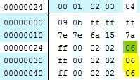
The Holden radios already have the NAV button but G8 radios have a power button in place of the NAV button. So the G8 Radio and fascia EEPROMS were changed to enable the Nav button/RGB input. For the radio, 3 locations at offset 024, 034, 044 were changed from 0B to 06 (see pic below). On the fascia, offset at 034 was changed from 0B to 06. I only tried this on my V9 radio. Not sure if other radio versions are different. Once the EEPROM updates are done, 3 fascia buttons will be remapped.
1) The power button will now be a NAV button.
2) The menu button will now be the Volume and Power button
3) The volume button will be the Menu button.
Now, to keep the RGB input "alive", a GMLAN message will need to be sent. Luckily a few guys over at Carmodder already did this legwork. Big thanks to TMK, ZerOne and Jezzab for data logging, analyzing the logs and determining what message needed to be sent. Carmodder thread is here. Message needed (add to Arduino program) is can_send_29bit_message(0x102e2094, 0x25, 0x00, 0x00, 0x00, 0x00, 0x00, 0x00, 0x00, 0x00);
You will need an Arduino and Canbus shield. I'm not going to go into detail on how to use an Arduino. You are on your own for this. However, a good GMLAN Arduino program can be found here: https://github.com/Afterglow/arduino-gmlan
Now that the RGB input is active, you need something to connect to it and a touchscreen overlay to control it! I already had a WinCE navigation box from Car Solutions called CS9200 that has long been discontinued. They have newer versions of this and also Android nav boxes as well. You will also need a video cable of course that connects to the side of the radio. I have the pinout info somewhere. I'll post it when I find it.
For the touchscreen overlay, I used a 6.5" 4 wire resistive screen overlay, touchscreen controller and optional adapter cable from TVI Electronics.
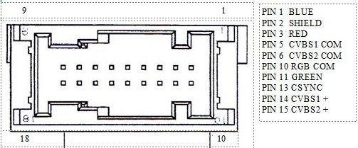
Video Connector info Pinouts. This is also known as the rear aux or VIM connector. Most people have one of these by now. You will need to add 5 leads/wires to this connector.
Pin 1 Blue
Pin 3 Red
Pin 10 Ground
Pin 11 Green
Pin 13 Sync
I am using an Arduino Uno and a Sparkfun Canbus shield. There is a DB9 connector on the canbus shield. From here you will need to connect to Power, Ground and CAN. You will need to make a harness to connect from the DB9 connector to the unused 16 pin connector under/behind the glovebox. I used an enclosure for the Arduino/shield and put it in the glove box along with the Nav box I used so everything is tucked away and not visible.
DB9 pinout info. Since the G8 radio uses Single Wire CAN (Not CAN L(low) and CAN H (high)), in order for the Arduino/Canbus shield to properly communicate with the vehicle, the CAN L pin will need to be tied to Ground and the CAN H line will be used to connect to the GMLAN signal.
Link for the CAN shield schematic on Sparkfun's website:
https://cdn.sparkfun.com/datasheets/...hield_v13a.pdf
Pin 3 of DB9 (CAN H) --> Pin 4 (GMLAN) of 16 Pin connector
Pin 2 of DB9 (Ground) --> Pin 10 (Ground) of 16 Pin connector
Pin 9 of DB9 (Power) --> Pin 5 (Acc. Voltage) of 16 Pin connector
Pin 5 of DB9 CAN L --> Pin 2 of DB9 Ground
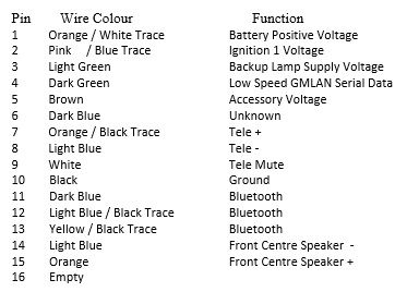
16 Pin connector Pinout. Not all of these wires are available in the G8.
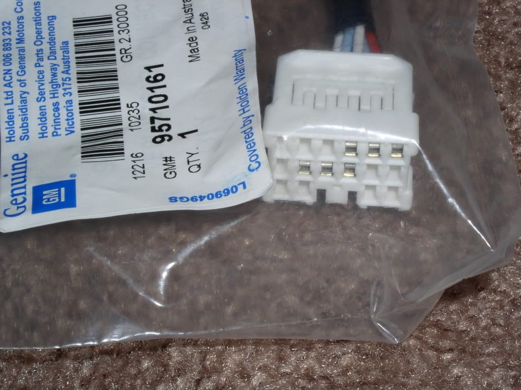
For the 16 pin connector, I already had one from when I did my backup cam install several years ago (connected to here for camera power, ground, reverse signal). Yazaki connector is 7283-1160 and terminals 7116-4020. Not sure of availability of these anymore. As an alternative, GM makes a connector with several leads already.
Last edited by BlackGT5; 06-03-2018 at 04:30 PM. Reason: Corrected DB9 pinout info
Very detailed. Thanks for posting.
Rest in Peace Charlie!
Sold
Just a GT
Originally Posted by RichsGreyGT

Posting Permissions

 Reply With Quote